- Home
- -
- Products
- -
- Ship Navigation Equipment
- -
- FURUNO ARPA RADAR series FAR-2117 I 2817 I FAR-2127W I 2827W I FAR-2117 I 2837S


FURUNO ARPA RADAR series FAR-2117 I 2817 I FAR-2127W I 2827W I FAR-2117 I 2837S
FURUNO ARPA RADAR series FAR-2117 I 2817 I FAR-2127W I 2827W I FAR-2117 I 2837S USED RADAR ALANG INDIA
FURUNO ARPA Radar FAR-28x7 series and FAR-21x7 series fully meet the latest performance standards of IMO and IEC for all ships and for ships under 10,000 GT, respectively. It is designed to meet the demands of today's maritime industry.
The FAR-21x7/28x7 series radar has DVI (Digital Video Interface) facility integrated to deliver crisp and clear radar images. Target detection is enhanced by sophisticated signal processing techniques featuring superb short range detection. AIS information scheme can be incorporated when AIS transponder/receiver is interfaced, thereby further enhancing situation awareness of the operators. FURUNO ARPA Radar FAR-21x7/28x7 series brings greater bridge performance and enhanced navigation accuracy, increasing both operating efficiency and safety level at sea.
Features
Here is the list of antenna selection for FURUNO ARPA Radar FAR-21x7/28x7 series.
| FAR-2117/2817 | X-band, 12 kW, TR up |
| FAR-2127/2827 | X-band, 25 kW, TR up |
| FAR-2827W | X-band, 25 kW, TR down |
| FAR-28137S/2837S | S-band, 30 kW, TR up |
| FAR-2837SW | S-band, 30 kW, TR down |
X-band antenna for FAR-2117/2817/2127/2827/2827W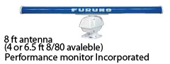 | S-band antenna for FAR-2137S/2837S/2837SW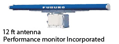 |
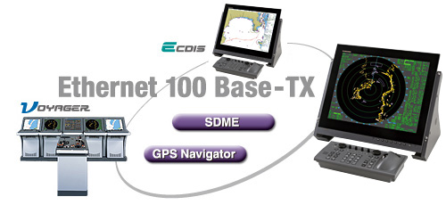
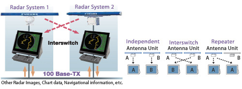
100 Base-TX Ethernet Network System
The 100 Base-TX Ethernet is utilized to network up to four sets of FAR-21x7/28x7 series radar with ECDIS FEA-2107/2807. This Ethernet data link gives high-speed and stable navigational data sharing amongst the equipment networked within the system. This network capability gives options to choose from a single station system configuration to complete Integrated Navigation System (INS).
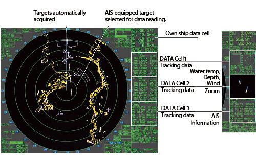
Target Tracking(TT: ARPA)/AIS
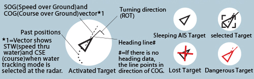
The FAR-21x7/28x7 series radar delivers full TT functionality and can plot up to 100 targets. In addition, this radar series is displaying up to 1,000 targets received from the AIS transponder system. Detailed information about the targets can be shown in data cells on right hand side of the screen. TT/AIS information Scheme gives the operator full control over dense traffic. The type of AIS Symbol shows if it is a sleeping target, a normal target, a selected target, a dangerous target or a lost target.
AIS Symbols
COG/SOG vector changes its length with speed. ROT mark is viewable at the COG/SOG vector tip when a target has FURUNO Satellite Compass SC-50/110 or gyrocompass, which deal ROT serial sentence, installed.
Guard Zones
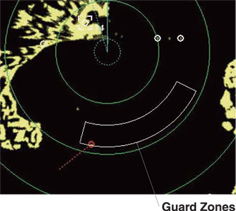
Automatic Acquisition Zones
Two automatic acquisition zones can be set in a sector or in any form. These zone act as suppression zones, avoiding unnecessary overloading to the processor and clutter by disabling automatic acquisition and tracking outside them. Targets in an automatic acquisition zone are shown with an inverse triangle. The operator can manually acquire important targets without restriction, an essential aid and source of information on assessing the situation.
Guard Zones and Anchor Watch Zone
Guard Zones generate visual and audible alarms when targets entered the operator-set zones. One of the Guard Zones can be used as an anchor watch to alert the operator when own ship or targets drift away from the set zone.
CPA Alarm
The target tracking symbol changes to a triangle when its predicted course violates the operator-set CPA/TCPA so that the operator may be notified of the approaching targets to the own ship for collision avoidance. The operator can readily change the vector lengths to evaluate the target movement trend.
Target Trails
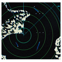 Target trail feature generates a monotone or gradual shading afterglow on all objects on the display in order to help clarify traffic situation. Echo trails can be displayed in either true or relative motion (only true trail on TM). Relative trails show relative movements between targets and own ship. True motion trails require a gyrocompass signal and own ship speed input to cancel own ship's movement and present true target movements in accordance with their over-the-ground speeds and courses.
Radar Map
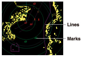 A radar map is a combination of lines and marks whereby the operators can define and input the navigation area and route planning/monitoring data. The radar map can include up to 20,000 points for lines and marks. The map data can be saved to facilitate repeated use on a regular navigation area. Planned routes created on ECDIS can be transferred onto a radar display when networked with ECDIS.
Stress-free Operation through Ergonomically-designed Control Unit
The control head has logically arranged operation Scheme through a combination of push keys and a trackball. Well-organized menus ensure that all operations can be performed with a trackball.
Full-keyboard control head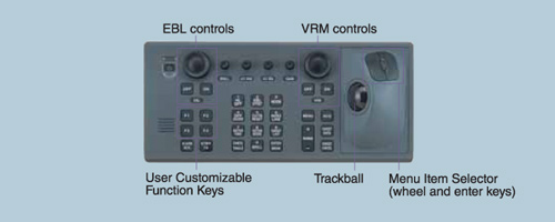
Trackball control head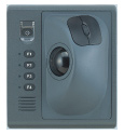 Alternative to the Full-keyboard type or additional control head to be placed close to captain chair for remote operation.